
Page 33 - Analysis Report of Global Market in the Submarine Cable Field (2017)
P. 33
as good shielding effect. If the sensitivity of the sensors was far too low, the main drawback is low sensitivity, this is largely limited to its use in
there will havesome PD signals that can’t be detected; If the bandwidth power systems, Usually, it’s only serves as an auxiliary method to locate
is very narrow, PD signals may be distorted; If the shield system is not the defect. In actual engineering projects, we can combine the VHF
perfect, PD signals may be contaminated by the noise. To solve these technology and the AE technology to complete the detection of partial
problems, we can symmetry install magnetic core current transformer discharge in power system. VHF and AE are in different frequency
on the secondary side. bands, Compared with the signals of the two methods, it's not hard to
draw a conclusion. For different PD signals, the spectrum they present
Pic 2 ( Rogowski coil)
is different, the spectrum of the same PD signal in AE and VHF is
very similar. By comparing the twospectrum, it meets the requirement
of electromagnetic interference and the demand of sensitivity at the
same time, so the position of defects in the power system can be found
precisely.
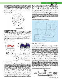
Pic 4 AE for the partial discharge in transformer
3.3 Ultra high frequency method
The UHF signal is aultra highfrequency radio wave, the frequency is 300
~ 3000MHz. The partial discharge signal received by the sensor is mainly
concentrated in 500 ~ 1500MHz. The Uhf method can inhibit most of
the external interference signals, this because most of the interference
signals are less than 400MHz. The signals needs to be amplified by the
UHF amplifier. Uhf method can be applied for many places, like in the
high voltage metal closed switch equipment, power transformer and in
power distribution substation.
Pic 3 UHF schematic diagram
3.5 Capacitive coupling method
This method is using coupling capacitor to detect the partial discharge in
the cable line. The sensor used in this method has two types: interior and
external. Capacitance coupling method has highly sensitive in various
methods of the PD measurement. The sensitivity can reach 10pC.
Capacitance coupled sensors are measured in range of about 100kHz ~
300MHz, however, the noise in this frequency is relatively complex and
serious, this method is susceptible to noise interference. The external
capacitive coupling sensor has a higher sensitivity than high-frequency
current sensor, can provide more typical partial discharge model. In
addition, the external capacitive coupling sensor can be installed in
any position, installation and disassembly is very convenient. External
sensors are usually placed in cable or straight connections. Relatively
speaking, the internal capacitance coupling sensor is generally placed on
the outer semi-conductor layer. The sensitivity of the built-in capacitive
sensor depends on its installation status. The advantage of the built-in
capacitive coupling sensor is that the external interference can be better
3.4 Acoustic emission shielded, usually installed in ultra-high voltage cables and prefabricated
Acoustic emission technology is collect discharge signals from AE sensors joints, in particular, it can be installed at the head of the high-voltage
which installed on the cable joint, the signals include sound signals and cable system which is connected in three phases. Compared with the
ultrasonic signals, both are elastic waves. The AE sensor can easily detect Rogowski coil, capacitive sensors can be installed more conveniently and
the elastic waves generated in dielectric by partial discharge activity, quickly on the cable interconnection box.
however, the AE sensor can hardly estimate the charge of the discharge,
so the deterioration degree of the insulation cannot be determined. Pic 5 Schematic diagram of signal circuit measurement
Studies have shown that, the signal detected by AE in the cable joint
is obviously attenuated. Because sound wave and ultrasonic wave will
have stronger attenuation in the transmission process, it is difficult to
calculate its decrease. When the partial discharge signal is farther away
from AE sensor, the detection result may be more error.The greatest
advantage of AE technology is that can effectively resist electromagnetic
interference, easy to install and can identify the defect locationprobably,
continuing to pag 24 33